<?xml version="1.0" encoding="utf-8"?><feed xmlns="http://www.w3.org/2005/Atom" ><generator uri="https://jekyllrb.com/" version="3.10.0">Jekyll</generator><link href="http://danielbroback.se//feed.xml" rel="self" type="application/atom+xml" /><link href="http://danielbroback.se//" rel="alternate" type="text/html" /><updated>2026-07-18T13:11:41+00:00</updated><id>http://danielbroback.se//feed.xml</id><title type="html">Dannebrob</title><subtitle>Networking, Automation and Cybersecurity</subtitle><author><name>Daniel Brobäck</name></author><entry><title type="html">OSFP Troubleshooting (CML-bitsize-labs)</title><link href="http://danielbroback.se//CML-bitsize-labs-OSFP-Troubleshooting/" rel="alternate" type="text/html" title="OSFP Troubleshooting (CML-bitsize-labs)" /><published>2026-06-23T00:00:00+00:00</published><updated>2026-06-23T00:00:00+00:00</updated><id>http://danielbroback.se//CML-bitsize-labs-OSFP-Troubleshooting</id><content type="html" xml:base="http://danielbroback.se//CML-bitsize-labs-OSFP-Troubleshooting/"><![CDATA[<p>This lab is part of the Bitsize series, where you are set out to troubleshoot the network to find out why OSPF are malfunctioning.</p>

<h1 id="ospf-stub-areas">OSPF Stub Areas</h1>
<p>You will find all the labs in the Bitsize series on my GitHub, link to repo: <a href="https://github.com/dannebrob/CML-bitsize-labs/tree/main">CML-bitsize-labs</a>.</p>

<h2 id="learning-objectives">Learning Objectives</h2>
<ul>
  <li>Real-world troubleshooting in a small network</li>
  <li>Verify OSPF configurations.</li>
  <li>Ticket documentation</li>
</ul>

<h2 id="lab-overview">Lab Overview</h2>
<p>This is a short one, a quick troubleshooting lab to test your skills to find the errors and practice how to handle it like a real-world ticket.</p>

<p>If you need to brush up on the concepts, I have some study notes that you are more than welcome to review, here is the <a href="https://github.com/dannebrob/CCNP-study-notes">link</a>, I’m sure it will help you in your journey towards mastering OSPF, OSPF stub areas and virtual links.</p>

<h2 id="design-decisions">Design decisions</h2>
<p>This lab is designed to give you hands-on experience with troubleshooting OSPF. The lab topology is designed to be simple and easy to understand, while still providing enough complexity to allow you to practice the concepts of OSPF.</p>

<h2 id="lab-instructions">Lab Instructions</h2>
<ol>
  <li><strong>Setup</strong>: Clone the lab repository and navigate to the <code class="language-plaintext highlighter-rouge">./ospf/03-Troubleshooting</code> folder. Review the provided startup configurations for the routers in the lab topology.</li>
  <li><strong>Configuration</strong>: Import the <code class="language-plaintext highlighter-rouge">03-OSPF_Troubleshooting_Lab.yaml</code> file into the CML environment. 
Follow the instructions in the Lab Tasks to troubleshoot the OSPF on all the appropriate routers. Use the CLI to apply the necessary commands and verify your configuration.</li>
  <li><strong>Testing</strong>: After the troubleshooting, test the network connectivity to ensure that the hosts are able to comunicate with eachother.</li>
</ol>

<h2 id="lab-tasks">Lab Tasks</h2>
<ol>
  <li><strong>Review the Lab Environment</strong>: Familiarize yourself with the lab environment and the routers involved.</li>
  <li><strong>Review the ticket</strong>: Read the ticket <code class="language-plaintext highlighter-rouge">ticket.txt</code> found in the folder.</li>
  <li><strong>Solve the ticket and document the changes</strong>: Verify configuration as you go along and document the changes in the <code class="language-plaintext highlighter-rouge">lab-notebook.txt</code>, you should also include the show commands you use to verify the configuration.</li>
</ol>

<h2 id="walkthrough">Walkthrough</h2>

<ol>
  <li>
    <p><strong>Review the Lab Environment</strong>: When looking at the lab, you will see five devices. Two hosts (Ubuntu1 and Ubuntu3) in respective subnets, and three routers that make up the OSPF network: R1, R2 and R3.</p>
  </li>
  <li>
    <p><strong>Review the Ticket</strong>: The ticket describes a real-world issue where East Campus users cannot reach shared resources. This is a vague service desk ticket with no technical details—typical of production incidents.</p>
  </li>
  <li><strong>Verify Basic Connectivity</strong>:
    <ul>
      <li>From Ubuntu1, attempt to ping Ubuntu3: <code class="language-plaintext highlighter-rouge">ping 192.168.3.10</code></li>
      <li>Expected: Should fail with “Destination host unreachable”</li>
      <li>This confirms the issue exists</li>
    </ul>
  </li>
  <li><strong>Check OSPF Neighbor Adjacencies</strong>:
    <ul>
      <li>SSH into R1 and run: <code class="language-plaintext highlighter-rouge">show ip ospf neighbor</code>
        <ul>
          <li>Should see R2 (1.1.1.1) in FULL state ✅</li>
        </ul>
      </li>
      <li>SSH into R2 and run: <code class="language-plaintext highlighter-rouge">show ip ospf neighbor</code>
        <ul>
          <li>Should see R1 (1.1.1.1) in FULL state ✅</li>
          <li>Should see R3 (3.3.3.3) in EXSTART or EXCHANGE state ❌ (BUG!)</li>
        </ul>
      </li>
      <li>SSH into R3 and run: <code class="language-plaintext highlighter-rouge">show ip ospf neighbor</code>
        <ul>
          <li>Should see R2 (2.2.2.2) in EXSTART or EXCHANGE state ❌ (BUG!)</li>
        </ul>
      </li>
    </ul>
  </li>
  <li><strong>Diagnose the R2↔R3 Adjacency Failure</strong>:
    <ul>
      <li>On R2, run: <code class="language-plaintext highlighter-rouge">show ip ospf interface Ethernet0/1</code>
        <ul>
          <li>Check the “Network Type” field</li>
          <li>Should show: <code class="language-plaintext highlighter-rouge">POINT_TO_MULTIPOINT</code></li>
        </ul>
      </li>
      <li>On R3, run: <code class="language-plaintext highlighter-rouge">show ip ospf interface Ethernet0/0</code>
        <ul>
          <li>Check the “Network Type” field</li>
          <li>Should show: <code class="language-plaintext highlighter-rouge">BROADCAST</code> (default)</li>
        </ul>
      </li>
      <li><strong>Root Cause #1 Found</strong>: Network type mismatch prevents adjacency formation</li>
    </ul>
  </li>
  <li><strong>Fix Bug #1 - Network Type Mismatch</strong>:
    <ul>
      <li>On R3, enter configuration mode:
 R3# configure terminal
 R3(config)# interface Ethernet0/0
 R3(config-if)# ip ospf network broadcast
 R3(config-if)# end</li>
      <li>Verify the change:
 R3# show ip ospf interface Ethernet0/0
 (Network Type should now show BROADCAST)</li>
      <li>Wait 30-40 seconds for adjacency to form</li>
      <li>Verify on R2: <code class="language-plaintext highlighter-rouge">show ip ospf neighbor</code> (R3 should now be FULL)</li>
    </ul>
  </li>
  <li><strong>Check OSPF Database for Missing Routes</strong>:
    <ul>
      <li>On R1, run: <code class="language-plaintext highlighter-rouge">show ip ospf database</code>
        <ul>
          <li>Look for loopback 3.3.3.3 in Area 0</li>
          <li>It should now appear (was missing before)</li>
        </ul>
      </li>
      <li>Attempt ping again: <code class="language-plaintext highlighter-rouge">ping 192.168.3.10</code>
        <ul>
          <li>Still fails with “Destination host unreachable” ❌ (Second bug remains)</li>
        </ul>
      </li>
    </ul>
  </li>
  <li><strong>Diagnose Missing Routes in OSPF Database</strong>:
    <ul>
      <li>On R3, check the OSPF configuration:
 R3# show running-config | section router ospf</li>
      <li>Look for the network statement for the 192.168.3.0/24 subnet</li>
      <li>Should see something like: <code class="language-plaintext highlighter-rouge">network 192.168.3.0 0.0.255.255 area 2</code></li>
      <li><strong>Root Cause #2 Found</strong>: Wildcard mask <code class="language-plaintext highlighter-rouge">0.0.255.255</code> is incorrect for a /24 network (should be <code class="language-plaintext highlighter-rouge">0.0.0.255</code>)</li>
    </ul>
  </li>
  <li><strong>Fix Bug #2 - Incorrect Wildcard Mask</strong>:
    <ul>
      <li>On R3, enter configuration mode:
 R3# configure terminal
 R3(config)# router ospf 1
 R3(config-router)# no network 192.168.3.0 0.0.255.255 area 2
 R3(config-router)# network 192.168.3.0 0.0.0.255 area 2
 R3(config-router)# end</li>
      <li>Save configuration:
 R3# write memory</li>
    </ul>
  </li>
  <li><strong>Verify Both Fixes</strong>:
    <ul>
      <li>Check R3 configuration:
 R3# show running-config | include network
 (Should show correct wildcard: 0.0.0.255)</li>
      <li>Check OSPF database on R1:
 R1# show ip ospf database
 (Should now include 3.3.3.3 and 192.168.3.0/24 routes)</li>
      <li>Check routing table:
 R1# show ip route ospf
 (Should show route to 192.168.3.0/24)</li>
    </ul>
  </li>
  <li><strong>Final Verification - End-to-End Connectivity</strong>:
    <ul>
      <li>From Ubuntu1, ping Ubuntu3:
```
ubuntu1$ ping -c 4 192.168.3.10
PING 192.168.3.10 (192.168.3.10) 56(84) bytes of data.
64 bytes from 192.168.3.10: icmp_seq=1 ttl=62 time=4.2 ms
64 bytes from 192.168.3.10: icmp_seq=2 ttl=62 time=3.8 ms
64 bytes from 192.168.3.10: icmp_seq=3 ttl=62 time=4.1 ms
64 bytes from 192.168.3.10: icmp_seq=4 ttl=62 time=3.9 ms
— 192.168.3.10 statistics —
4 packets transmitted, 4 received, 0% packet loss ✅ SUCCESS</li>
      <li>From Ubuntu3, ping Ubuntu1:
ubuntu3$ ping -c 4 192.168.1.10
(Should also succeed with 0% packet loss)
```</li>
    </ul>
  </li>
  <li><strong>Document the Solution</strong>:
    <ul>
      <li><strong>Bug #1</strong>: R2 Ethernet0/1 configured with <code class="language-plaintext highlighter-rouge">ip ospf network point-to-multipoint</code> while R3 Ethernet0/0 used default <code class="language-plaintext highlighter-rouge">broadcast</code> type. This prevented OSPF adjacency formation.</li>
      <li><strong>Bug #2</strong>: R3 OSPF network statement used incorrect wildcard mask <code class="language-plaintext highlighter-rouge">0.0.255.255</code> instead of <code class="language-plaintext highlighter-rouge">0.0.0.255</code> for the 192.168.3.0/24 subnet, preventing the subnet from being advertised into OSPF.</li>
      <li><strong>Resolution</strong>: Changed R3 E0/0 network type to broadcast and corrected the wildcard mask. Both routers now have complete OSPF databases and all subnets are reachable.</li>
    </ul>
  </li>
  <li><strong>Ticket Resolution</strong>:
    <ul>
      <li>Update ticket with findings</li>
      <li>Mark as RESOLVED</li>
      <li>East Campus users can now access shared resources</li>
    </ul>
  </li>
</ol>]]></content><author><name>Daniel Brobäck</name></author><category term="03-troubleshooting" /><summary type="html"><![CDATA[This lab is part of the Bitsize series, where you are set out to troubleshoot the network to find out why OSPF are malfunctioning.]]></summary></entry><entry><title type="html">Replace printer in Catalyst Center MAB (CML-bitsize-labs)</title><link href="http://danielbroback.se//CML-bitsize-labs-Replace-printer-in-Catalyst-Center-MAB/" rel="alternate" type="text/html" title="Replace printer in Catalyst Center MAB (CML-bitsize-labs)" /><published>2026-05-07T00:00:00+00:00</published><updated>2026-05-07T00:00:00+00:00</updated><id>http://danielbroback.se//CML-bitsize-labs-Replace-printer-in-Catalyst-Center-MAB</id><content type="html" xml:base="http://danielbroback.se//CML-bitsize-labs-Replace-printer-in-Catalyst-Center-MAB/"><![CDATA[<p>This is a walkthrough-lab, with some inspiration taken from a real world situation. We were in need of replacing a printer in the network: But I did not get the chance to do it in the production network, so I created this lab to test it out in the Devnet Sandbox environment. This was a great opportunity to test the integration between ISE and Catalyst Center, and to see how MAB works in a real world scenario.</p>

<h1 id="replace-printer-in-catalyst-center-with-mab">Replace printer in Catalyst Center with MAB</h1>

<h2 id="lab-overview">Lab Overview</h2>
<p>The printer that will be added will be named Printer1. The task was to ensure that the new printer would be authenticated via MAB and placed in the correct VLAN (VLAN 30 for printers) in the network, and that this information would be visible in Catalyst Center. The lab is designed to simulate the process of adding a printer to a network that uses Cisco Identity Services Engine (ISE) for authentication and Cisco Catalyst Center for network management and visibility. Since both ISE and Catalyst Center is located outside of my regular homelab this lab will be more of a walkthrough that a hands-on lab that will test your capabilities. Still, just follow the steps and you will be able to complete the lab and learn how to MAB a printer in ISE with the help of Catalyst Center, and how to verify that the printer is authenticated and placed in the correct VLAN in Catalyst Center.</p>

<h3 id="want-more-labs">Want more labs?</h3>
<p>You will find all the labs in the Bitsize series on my Github, link to repo: <a href="https://github.com/dannebrob/CML-bitsize-labs/tree/main">CML-bitsize-labs</a>.</p>

<h2 id="learning-objectives">Learning Objectives</h2>
<ul>
  <li>Identify client devices at the switch level</li>
  <li>Understand MAC address tables and authentication sessions</li>
  <li>Familiarize yourself with Catalyst Center and ISE</li>
  <li>Manage endpoints in Cisco ISE</li>
  <li>Create and apply ISE authorization policies</li>
  <li>Assign VLANs via MAB</li>
  <li>Troubleshoot the end-to-end NAC flow</li>
</ul>

<h2 id="lab-instructions">Lab Instructions</h2>

<p><strong>Prerequisites</strong>:</p>
<ul>
  <li>Basic understanding of Cisco ISE and Catalyst Center</li>
  <li>An account on the Devnet Sandbox and access to the “Identity Services Engine 3.4” and “Catalyst Center Sandbox” or “Catalyst Center Always On” sandboxes.</li>
</ul>

<p><strong>Setup</strong>: Sign in to the Devnet Sandbox start page and reserve/launch the “Identity Services Engine 3.4” and the “Catalyst Center Sandbox” sandbox. Once the sandboxes is up and running and accessible, access the Catalyst Center GUI and the ISE GUI using the provided credentials. If you are using Windows you need to use AnyConnect client to connect to the VPN to access the sandbox.</p>

<p><strong>Configuration</strong>:
Follow the instructions in the Lab Tasks to configure ISE and Catalyst Center. Use the CLI to apply the necessary commands and verify your configuration.</p>

<h2 id="lab-tasks">Lab Tasks</h2>
<ol>
  <li>
    <p><strong>Identify the Networks</strong>: Familiarize yourself with ISE and Catalyst Center in the devnet sandbox. The MAC address of printer1 is 1111.1111.1111, and it is connected to the switch port Gi1/0/12.</p>
  </li>
  <li>
    <p><strong>Configure ISE</strong>: Create the necessary groups, endpoints, and authorization policies in ISE to allow the printer to authenticate via MAB and be placed in VLAN 30.</p>
  </li>
  <li>
    <p><strong>Configure and Verify Catalyst Center</strong>: 
Configure Catalyst Center to check the printer’s authentication and VLAN assignment. Verify that Catalyst Center is properly integrated with ISE and that it can see the printer’s authentication status and VLAN assignment.</p>
  </li>
</ol>

<h2 id="walkthrough">Walkthrough</h2>
<p>This is a walkthrough of the lab, where you can find the commands and steps to complete the lab tasks.</p>

<p>### Identify the Networks
 Sign up to the Devnet Sandbox and review the lab topology to understand the network setup. Identify the switches, printers, and the ISE server that will be involved in the lab.</p>

<p><strong>Look up the mac address of printer1</strong>: 
Access the switch that the printer is connected to, you can find the switch in the inventory of Catalyst Center, and use the Run Command feature to find the MAC address of printer1. To find the Inventory go to the main menu of Catalyst Center → Provisioning → Inventory. 
In the Command Runner, input the following command: show mac address-table and locate the MAC address of printer1. The output will be something like this:</p>

<div class="language-plaintext highlighter-rouge"><div class="highlight"><pre class="highlight"><code>          Mac Address Table
-------------------------------------------
Vlan    Mac Address       Type        Ports
----    -----------       --------    -----
      1111.1111.1111    DYNAMIC     Gi1/0/12
</code></pre></div></div>

<h3 id="configure-ise">Configure ISE:</h3>
<p>Log in to the ISE GUI with your browser and sign in with the provided credentials given in an email sent from your friends at Cisco.</p>

<p><strong>Create MAB Group</strong>: 
First you need to create a group for the printers in ISE, this will help you to apply specific policies for the printers.
Navigate to Administration → Identity Management → Groups → Add. Create a group named <strong>“Printers”</strong> and save it.</p>

<p><img src="https://i.ibb.co/M58HMkmB/image.png" alt="ise-groups" /></p>

<p><strong>Create Endpoint</strong>:
Next, you need to create an endpoint for the printer in ISE. This will allow you to manage the printer’s authentication and authorization policies.
We already have the MAC address of printer1, so we will use that to create the endpoint.
Navigate to Context Visibility → Endpoints → Add. Create an endpoint with the following details:
<br />
mac address: 1111.1111.1111
<br />
Static Group Assignment: Printers
<br />
<br />
<img src="https://i.ibb.co/VYBmHTSm/image.png" alt="Add endpoint screenshot" />
Save the endpoint.</p>

<p><strong>Create Dynamic VLAN Profile</strong>:
Now you need to create a dynamic VLAN profile that will assign the printer to VLAN 30 when it authenticates via MAB.
Navigate to Policy → Results → Authorization → Authorization Profiles → Add. Create an authorization profile with the following details:
Name: Permit_VLAN_30
Common Tasks → VLAN: → ID/name: 30
Save the profile.</p>

<p><img src="https://i.ibb.co/W4hQC7Gb/image.png" alt="Authorization profile screenshot" /></p>

<p><strong>Create new Policy Set</strong>:
Add a new Policy Set for the printer, this will allow you to apply the authorization profile to the printer when it authenticates.
Navigate to Policy → Policy Sets → Add.</p>

<p>Name the policy set “Printer Policy Set” and click on the plus icon in the Conditions field to add a new condition.</p>

<p>This will open the Conditions Studio. Drag the Wired_MAB condition from the Library to the new under the Editor section.
Now save.</p>

<p><img src="https://niksec.com/configuring-cisco-ise-mab-policy-sets/conditions-studio.png" alt="Add condition screenshot" /></p>

<p>Now you will get back to the Policy Set page, giving you an overview of the newly created Policy Set. Make sure that <strong>Default Network Access</strong> is used in the Allowed Protocols / Server Sequence column. Save that as well.
A check will be preformed to verify that the policy set is valid. 
<img src="https://i.ibb.co/6c4NnrYY/image.png" alt="Add policy set screenshot" /></p>

<p>Continue in the Policy Set page, click on the arrow to the right of the <strong>Printer Policy</strong> Set (under the Vew column) to open the policy set.
Under the <strong>Authorization Policy</strong> tab, create a new rule by clicking on the plus icon. Name the rule “Printer MAB Rule” and click on the plus icon in the Conditions field to add a new condition.
In the Conditions Studio, in the Editor section, click on <strong>“Click to add an attribute”</strong> and click on <strong>“Identity Group”</strong> and select <strong>“IdentityGroupe”</strong> with attribute <strong>“Name”</strong>. On it check so it is marked as <strong>“Equals”</strong> and pick the value <strong>“Endpoint Identity Groupe:Printers”</strong>. Click on Use. 
Now you will get back to the Authorization Policy page. 
Next to the Conditions field click on Select from list in the profile column. Select the <strong>“Permit_VLAN_30”</strong> profile that we created earlier and click on Use.
Now save the rule and the policy set.</p>

<p>We also have to ensure that the <strong>Authentication Policy</strong> is properly configured to allow MAB authentication. Navigate to the Authentication Policy tab in the same policy set and ensure that there is a rule that allows MAB authentication for wired devices. If there isn’t, create a new rule that allows MAB authentication for wired devices. The role should look something like this: Identity Group equals Printer Policy Set: Default Network Access: Wired_MAB.</p>

<h3 id="configure-catalyst-center">Configure Catalyst Center:</h3>
<p><strong>Verify ISE Integration</strong>:
Before we can verify the printer’s authentication and VLAN assignment in Catalyst Center, we need to ensure that Catalyst Center is properly integrated with ISE. This involves checking the connection status and ensuring that endpoint synchronization is enabled.
Navigate to System → Settings → External Services → Authentication and Policy Servers in Catalyst Center. Here you should see the ISE server listed with a status of “Connected”. If it is not connected, you may need to troubleshoot the connection between Catalyst Center and ISE.</p>

<p><strong>Verify Port Configuration</strong>:
Navigate to Provisioning → Inventory in Catalyst Center and locate the switch and port that the printer is connected to (Gi1/0/12). Check the port configuration to ensure that it is set to allow MAB authentication and that it is not statically assigned to a different VLAN.
It should look something like this:</p>
<div class="language-plaintext highlighter-rouge"><div class="highlight"><pre class="highlight"><code>Port: Gi1/0/12
Admin State: Up
Operational State: Connected
Access Mode: Access
Authentication: MAB
VLAN: 30 (after authentication)
</code></pre></div></div>

<p><strong>Visualize the Authentication Status</strong>:
Navigate to Assurance → Health → Clients in Catalyst Center. Here you should see the printer listed as a client device. Click on the printer’s entry to view detailed information about its authentication status, VLAN assignment, and the switch port it is connected to.</p>

<h3 id="test-connectivity">Test Connectivity:</h3>
<p>In a real world scenario, you would now connect the printer to the network and verify that it authenticates via MAB and is placed in VLAN 30. You can use the Catalyst Center GUI to check the client’s status and ensure that it is correctly authenticated and assigned to the right VLAN. Ping the printer from another device in the same VLAN can also be used to verify connectivity.</p>

<h1 id="the-end">The End</h1>
<p>That’s it for this lab! You have successfully replaced a printer in the network using MAB authentication and used Catalyst Center to manage the configuration.
If this was helpful in any way or even the slightest bit interesting, I’m a sucker for feedback, so please let me know if you have any suggestions or improvements. Please reach me on Github or Linkedin.</p>

<h2 id="resources">Resources</h2>
<ul>
  <li><a href="https://niksec.com/configuring-cisco-ise-mab-policy-sets/">NiKSec.com; Configuring Cisco ISE MAB Policy Sets</a></li>
  <li><a href="https://developer.cisco.com/site/sandbox/">Cisco Devnet Sandbox</a></li>
  <li><a href="https://www.cisco.com/c/en/us/support/security/identity-services-engine/series.html">Cisco ISE Documentation</a></li>
  <li><a href="https://www.cisco.com/c/en/us/support/switches/catalyst-center/series.html">Cisco Catalyst Center Documentation</a></li>
</ul>]]></content><author><name>Daniel Brobäck</name></author><category term="01 - mab" /><summary type="html"><![CDATA[This is a walkthrough-lab, with some inspiration taken from a real world situation. We were in need of replacing a printer in the network: But I did not get the chance to do it in the production network, so I created this lab to test it out in the Devnet Sandbox environment. This was a great opportunity to test the integration between ISE and Catalyst Center, and to see how MAB works in a real world scenario.]]></summary></entry><entry><title type="html">OSPF Stub Area Lab (CML-bitsize-labs)</title><link href="http://danielbroback.se//CML-bitsize-labs-OSPF-Stub-Area-Lab/" rel="alternate" type="text/html" title="OSPF Stub Area Lab (CML-bitsize-labs)" /><published>2026-03-18T00:00:00+00:00</published><updated>2026-03-18T00:00:00+00:00</updated><id>http://danielbroback.se//CML-bitsize-labs-OSPF-Stub-Area-Lab</id><content type="html" xml:base="http://danielbroback.se//CML-bitsize-labs-OSPF-Stub-Area-Lab/"><![CDATA[<p>This lab is part of the Bitsize series, where we will be covering OSPF Stub Areas and Virtual Links. In this lab, we will be configuring OSPF Stub Areas in a network topology, and implementing Virtual Links to connect non-backbone areas to the backbone area. We will also be verifying our OSPF configurations and testing connectivity between different areas of the network.</p>

<h1 id="ospf-stub-areas">OSPF Stub Areas</h1>
<p>You will find all the labs in the Bitsize series on my GitHub, link to repo: <a href="https://github.com/dannebrob/CML-bitsize-labs/tree/main">CML-bitsize-labs</a>.</p>

<h2 id="learning-objectives">Learning Objectives</h2>
<ul>
  <li>Implement OSPF normal areas and Stub Areas in a network topology.</li>
  <li>Implement Virtual Links in OSPF to connect non-backbone areas to the backbone area.</li>
  <li>Verify OSPF configurations.</li>
  <li>Document the OSPF Stub Area configuration in the Lab notebook text file.</li>
</ul>

<h2 id="lab-overview">Lab Overview</h2>
<p>I’m glad you are here, in this lab we will be configuring OSPF Stub Areas in a network topology. We will also be implementing Virtual Links to connect a non-backbone area to the backbone area, and configuring OSPF to ensure connectivity with the rest of the network.</p>

<p>If you need to brush up on the concepts, I have some study notes that you are more than welcome to review, here is the <a href="https://github.com/dannebrob/CCNP-study-notes">link</a>, I’m sure it will help you in your journey towards mastering OSPF, OSPF stub areas and virtual links.</p>

<h2 id="design-decisions">Design decisions</h2>
<p>This lab is designed to give you hands-on experience with configuring OSPF Stub Areas and Virtual Links. The lab topology is designed to be simple and easy to understand, while still providing enough complexity to allow you to practice the concepts of OSPF Stub Areas and Virtual Links. I have tried to make the lab instructions simple enough to guide you through the configuration process, but I encourage you to not use this as an tutorial and keep you in the “tutorial hell”. For the sake of not making the lab too complex, we will be using a simple topology with only a few routers and areas, but it will still provide you with the opportunity to practice the concepts of OSPF Stub Areas and Virtual Links, but what this lacks is real-world complexity, which is something you probably won’t find in a real-world scenario. The lab is designed to be completed in a reasonable amount of time, while still providing you with the opportunity to learn and practice the concepts of OSPF Stub Areas and Virtual Links.</p>

<h2 id="lab-instructions">Lab Instructions</h2>
<ol>
  <li><strong>Setup</strong>: Clone the lab repository and navigate to the <code class="language-plaintext highlighter-rouge">02-OSPF-Stub-Areas</code> folder. Review the provided startup configurations for the routers in the lab topology.</li>
  <li><strong>Configuration</strong>: Import the <code class="language-plaintext highlighter-rouge">02-OSPF_Stub_Areas_Lab.yaml</code> file into the CML environment. 
Follow the instructions in the Lab Tasks to configure OSPF Stub Areas on the appropriate routers. Use the CLI to apply the necessary commands and verify your configuration.</li>
  <li><strong>Testing</strong>: After configuring stub areas, test the network connectivity and routing tables to ensure that the stub areas are working as expected.</li>
</ol>

<h2 id="lab-tasks">Lab Tasks</h2>
<ol>
  <li><strong>Review the Lab Environment</strong>: Familiarize yourself with the lab environment and the routers involved.</li>
  <li>
    <p><strong>Configure OSPF area 0-4</strong>: Configure the appropriate routers to be part of the stub areas, ensuring that they are correctly connected to the backbone area (Area 0). One of the areas should be a normal area (not stub), one should be a normal stub area, one should be a totally stub area and one should be a NSSA-TS. Verify configuration as you go along and document the changes in the <code class="language-plaintext highlighter-rouge">lab-notebook.txt</code>, you should also include the show commands you use to verify the configuration.</p>
  </li>
  <li>
    <p><strong>Configure Virtual Links</strong>: If necessary, configure virtual links to connect non-backbone areas to the backbone area. Verify the configuration.</p>
  </li>
  <li>
    <p><strong>Verify Configuration</strong>: Use OSPF commands to verify that the stub areas are correctly configured and that the routers are advertising the correct routes.</p>
  </li>
  <li><strong>Test Connectivity</strong>: Test the connectivity between different areas of the network to ensure that the OSPF Stub Areas are functioning correctly.</li>
</ol>

<h2 id="walkthrough">Walkthrough</h2>
<ol>
  <li>
    <p><strong>Review the Lab Environment</strong>: 
We have a total of 8 routers in this lab, R1, R2, R3, R4, R5, R6, R7 and R8. None of the routers are configured with OSPF, but they have at least IP addresses and subnet masks configured on their interfaces. The interfaces connecting the routers are using p2p links (/30). The routes have tags in CML with the area they should be configured with.</p>
  </li>
  <li>
    <p><strong>Configure OSPF Areas</strong></p>
    <ul>
      <li>backbone area (Area 0): R1 and R2
<br />
We first need to configure OSPF on R1 and R2, and assign them to Area 0.
Open up the CLI for R1 and R2 and enter the following commands:
<br /></li>
    </ul>
  </li>
</ol>

<div class="language-plaintext highlighter-rouge"><div class="highlight"><pre class="highlight"><code>R1:
router ospf 1
router-id 1.1.1.1
network 10.10.10.0 0.0.0.3 area 0

R2:
router ospf 1
router-id   2.2.2.2
network 10.10.10.0 0.0.0.3 area 0
</code></pre></div></div>

<ul>
  <li>Now we need to configure R3, R4 and R5 to be part of Area 1, We will configure Area 1 to be a normal area.
Open up the CLI for R2, R3, R4 and R5 and enter the following commands:
<br /></li>
</ul>

<div class="language-plaintext highlighter-rouge"><div class="highlight"><pre class="highlight"><code>R2:
router ospf 1
network 10.20.20.0 0.0.0.3 area 1
network 10.20.20.4 0.0.0.3 area 1

R3:
router ospf 1
router-id 3.3.3.3
network 10.20.20.8 0.0.0.3 area 1

R4:
router ospf 1
router-id 4.4.4.4
network 10.20.20.12 0.0.0.3 area 1

R5:
router ospf 1
router-id 5.5.5.5
network 10.20.20.8 0.0.0.3 area 1
network 10.20.20.12 0.0.0.3 area 1
</code></pre></div></div>
<p><br /></p>
<ul>
  <li>Now we need to configure R5 and R6 to be part of Area 2, and we will configure Area 2 to be a totally stubby area.
Open up the CLI for R5 and R6 and enter the following commands:</li>
</ul>

<div class="language-plaintext highlighter-rouge"><div class="highlight"><pre class="highlight"><code>R5:
router ospf 1
network 10.30.30.0 0.0.0.3 area 2
area 2 stub no-summary

R6:
router ospf 1
router-id 6.6.6.6
network 10.30.30.0 0.0.0.3 area 2
area 2 stub no-summary
</code></pre></div></div>
<ul>
  <li>We need to configure Area 3 on R3, as a NSSA:
<br /></li>
</ul>

<div class="language-plaintext highlighter-rouge"><div class="highlight"><pre class="highlight"><code>R3:
router ospf 1
network 10.40.40.0 0.0.0.3 area 3
area 3 nssa

R8:
router ospf 1
router-id 8.8.8.8
network 10.40.40.0 0.0.0.3 area 3
area 3 nssa
</code></pre></div></div>
<p><br /></p>
<ul>
  <li>And the last area, area 4, needs to be configured on R4, as a NSSA-TS:</li>
</ul>

<div class="language-plaintext highlighter-rouge"><div class="highlight"><pre class="highlight"><code>R4:
router ospf 1
network 10.50.50.0 0.0.0.3 area 4
area 4 nssa no-summary

R7:
router ospf 1
router-id 7.7.7.7
network 10.50.50.0 0.0.0.3 area 4
area 4 nssa no-summary
</code></pre></div></div>
<p><br /></p>

<ol>
  <li><strong>Configure Virtual Links</strong>: If necessary, configure virtual links to connect non-backbone areas to the backbone area.</li>
</ol>

<p>Since area 2, 3 and 4 are not directly connected to the backbone area (Area 0), they will need to configure with virtual links between R2 and the respective areas to connect them to Area 0.
Open up the CLI for respective routers and enter the following commands:</p>
<div class="language-plaintext highlighter-rouge"><div class="highlight"><pre class="highlight"><code>R2:
router ospf 1
area 1 virtual-link 5.5.5.5
area 1 virtual-link 4.4.4.4
area 1 virtual-link 3.3.3.3

R5:
router ospf 1
area 1 virtual-link 2.2.2.2

R4:
router ospf 1
area 1 virtual-link 2.2.2.2

R3:
router ospf 1
area 1 virtual-link 2.2.2.2
</code></pre></div></div>
<p>This will create a virtual link between the routers, allowing area 2,3 and 4 to be connected to Area 0 through Area 1. It’s easy to think of it as a tunnel between the routers, allowing OSPF to exchange routing information between the two areas.
It don’t matter if its a physical or virtual link, as long as the OSPF process is configured correctly, the routers will be able to exchange routing information and the network will function as expected.</p>

<ol>
  <li><strong>Verify Configuration</strong>: Use OSPF commands to verify that the stub areas are correctly configured and that the routers are advertising the correct routes.
    <ul>
      <li>You can use the <code class="language-plaintext highlighter-rouge">show ip ospf neighbor</code> command to verify that the routers are forming adjacencies with their neighbors and that the correct areas are being advertised.</li>
      <li>To confirm that area 2, 3 and 4 are stub areas, you can use the <code class="language-plaintext highlighter-rouge">show ip ospf</code> command to verify that the areas are configured as stub areas and that the correct routes are being advertised.</li>
      <li>You can also use the <code class="language-plaintext highlighter-rouge">show ip route</code> command to verify that the correct routes are being advertised and that the routing tables are correct.</li>
      <li>You can also use the <code class="language-plaintext highlighter-rouge">show ip ospf database</code> command to verify that the OSPF database is correct and that the correct routes are being advertised.</li>
      <li>You can also use the <code class="language-plaintext highlighter-rouge">show ip ospf interface</code> command to verify that the interfaces are correctly configured and that the correct areas are being advertised on the interfaces.</li>
    </ul>
  </li>
</ol>

<ul>
  <li>You can also use the <code class="language-plaintext highlighter-rouge">show ip ospf virtual-links</code> command to verify that the virtual links are correctly configured and that they are up and running. The virtual links work because all endpoints are ABRs and they share Area 1 as a normal transit area. Cisco IOS permits this even when the ABRs’ other areas are stub or NSSA types.</li>
</ul>

<ol>
  <li><strong>Test Connectivity</strong>: Test the connectivity between different areas of the network to ensure that the OSPF Stub Areas are functioning correctly.
    <ul>
      <li>You can use the <code class="language-plaintext highlighter-rouge">ping</code> command to test connectivity between different areas of the network. 
Ping from R1 to R6 should work, as well as pinging from R3 to R4, and from R5 to R6.
Ping from R1 to R7 should also work
Ping from R1 to R8 should also work</li>
      <li>You can also use the <code class="language-plaintext highlighter-rouge">show ip route</code> command to verify that the correct routes are being advertised and that the routing tables are correct.</li>
    </ul>
  </li>
</ol>]]></content><author><name>Daniel Brobäck</name></author><category term="02-ospf-stub-areas" /><summary type="html"><![CDATA[This lab is part of the Bitsize series, where we will be covering OSPF Stub Areas and Virtual Links. In this lab, we will be configuring OSPF Stub Areas in a network topology, and implementing Virtual Links to connect non-backbone areas to the backbone area. We will also be verifying our OSPF configurations and testing connectivity between different areas of the network.]]></summary></entry><entry><title type="html">Lab overview (CML Enterprice lab)</title><link href="http://danielbroback.se//CML-Enterprice-lab-lab-overview/" rel="alternate" type="text/html" title="Lab overview (CML Enterprice lab)" /><published>2026-03-06T00:00:00+00:00</published><updated>2026-03-06T00:00:00+00:00</updated><id>http://danielbroback.se//CML---Enterprice-lab-lab-overview</id><content type="html" xml:base="http://danielbroback.se//CML-Enterprice-lab-lab-overview/"><![CDATA[<p>This is the first post in the series of posts about my enterprise lab, this post will cover the overview of the lab, the design decisions I made, and the goals I have for this lab. I want to share my knowledge and experience with others who are interested in learning about enterprise network design and configuration, and I hope that this lab will be a valuable resource for anyone looking to enhance their networking skills. If you are a network engineer, a student, or just someone interested in learning about enterprise networks, this lab is for you.</p>

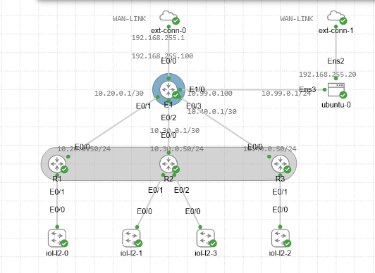
<h2 id="lab-overview-and-design-decisions">LAB OVERVIEW and DESIGN DECISIONS</h2>

<p><img src="/images/overview1.png" alt="OSPF Topology" /></p>

<p>Find the github repository for the lab files <a href="https://github.com/dannebrob/CML---Enterprice-lab">here</a></p>

<h3 id="what-is-this-lab-about-and-why-should-you-care">What is this lab about? And why should you care?</h3>

<p>This lab is about designing and configuring an enterprise network using Cisco Modeling Labs (<strong>Cisco CML</strong>). Cisco CML is a powerful network simulation tool that allows users to create and test network designs in a virtual environment. By simulating a real-world enterprise network environment, users can experiment with various configurations and scenarios without the need for physical hardware, making it an ideal learning tool for those looking to enhance their networking skills.</p>

<p>Throughout this lab I will be sharing my design decisions, the challenges I faced, and the solutions I implemented to overcome those challenges. This lab is not only a learning resource for others but also a personal project for me to test and learn new technologies in a practical setting.</p>

<h3 id="requirements">Requirements</h3>

<p>You fins the labfiles in the <a href="https://github.com/dannebrob/CML---Enterprice-lab">GitHub repository</a>, which includes the topology files, configuration files, and notes for each device in the lab. These files will be updated as I continue to work on the lab and add more devices and configurations.</p>

<p>To follow along with this lab, you will need to have access to Cisco Modeling Labs (Cisco CML with atleast Personal subscription) and a basic understanding of networking concepts, including routing protocols, switching, and network security. Familiarity with OSPF (Open Shortest Path First) will be particularly helpful, as it is the routing protocol used in this lab. Additionally, having some experience with network automation tools like Ansible will be beneficial, as I will be using Ansible for network management and automation in this lab. I will provide explanations to why I chose different technologies and configurations, but having a basic understanding of these concepts will help you get the most out of this lab and enhance your learning experience.</p>

<p>CML is hosted on a <strong>Proxmox</strong> server, if you want to set up a similar lab, you can follow the instructions in the Proxmox documentation to create a virtual environment for Cisco CML. Once you have Cisco CML set up, you can import the lab topology and configurations that I will be sharing in this series of posts.
I would recomend that you have a decent machine to run this lab,with atleast 8 CPU cores and 32 GB RAM as Cisco CML can be resource-intensive, especially when running multiple devices and complex configurations Also make sure to allocate enough of space for the imaes and configurations, I would recommend at least 500 GB of SSD storage for the lab. So in summary, the recommended hardware specifications for running this lab are:</p>

<p><strong>8–16 CPU‑kärnor, 32–64 GB RAM, och 500 GB SSD</strong></p>

<p>If you want an awesome installation guide of CML, you can check out this video <a href="https://www.youtube.com/watch?v=Ajpi_vVTtLc">Youtube link</a> by 0x2142 - Networking Nonsense, which provides a step-by-step guide to installing Cisco CML on Proxmox.</p>

<h3 id="goals">Goals</h3>

<p>My goal with this enterprise lab is to create a comprehensive and practical learning environment for network engineers and students who want to understand the intricacies of enterprise network design and configuration.</p>

<p>The lab will cover a wide range of topics, including routing protocols, switching, security, and network management. Each device in the lab will have its own notes file, which will provide detailed information about its role in the network, its configuration, and any relevant details that may be useful for understanding the lab. I will write these notes in a blogging style to make it easier for users to follow along and grasp the concepts being presented.</p>

<p>The design decision for the lab will be based on a typical enterprise network architecture, which includes edge routers, core routers, distribution switches, access switches, firewalls, and other network devices. The lab will also include various scenarios and configurations to help users understand how to design and configure an enterprise network effectively.</p>

<h3 id="routers-and-switches">Routers and switches:</h3>

<ul>
  <li>E1: This is the core router in the lab, which connects to the WAN and serves as the central point for routing traffic between different areas of the network. It will be configured with OSPF as the routing protocol and will have multiple interfaces connecting to the area routers (R1, R2, R3) and a DMZ for management and external access.</li>
  <li>R1: This is an area router that connects to E1 and serves as the gateway
for devices in Area 10. It will be configured with OSPF and will have interfaces connecting to E1 and the internal network.</li>
  <li>R2: This is another area router that connects to E1 and serves as the gateway
for devices in Area 20. It will also be configured with OSPF and will have interfaces connecting to E1 and the internal network.</li>
  <li>R3: This is the third area router that connects to E1 and serves as the gateway for devices in Area 30. It will be configured with OSPF and will have interfaces connecting to E1 and the internal network.</li>
  <li>Switches: The lab will also include various switches that connect to the area routers and provide connectivity for end devices in the internal network. These switches will be configured with VLANs and other features to simulate a real-world enterprise network environment.</li>
  <li>Firewalls: The lab will include firewalls that provide security for the internal network and the DMZ. These firewalls will be configured with access control lists (ACLs) and other security features to protect the network from external threats while allowing necessary traffic to pass through.</li>
</ul>

<h3 id="ip-plan">Ip plan:</h3>

<table>
  <thead>
    <tr>
      <th><strong>Device</strong></th>
      <th><strong>Interface</strong></th>
      <th><strong>IP Address</strong></th>
      <th><strong>Description</strong></th>
      <th><strong>OSPF Area</strong></th>
      <th><strong>RID</strong></th>
    </tr>
  </thead>
  <tbody>
    <tr>
      <td><strong>E1</strong></td>
      <td>Eth0/0</td>
      <td>192.168.255.100/24</td>
      <td>WAN / Proxmox host NIC</td>
      <td>0</td>
      <td>1.1.1.1</td>
    </tr>
    <tr>
      <td> </td>
      <td>Eth0/1</td>
      <td>10.20.0.1/30</td>
      <td>Link to R1</td>
      <td>10</td>
      <td> </td>
    </tr>
    <tr>
      <td> </td>
      <td>Eth0/2</td>
      <td>10.30.0.1/30</td>
      <td>Link to R2</td>
      <td>20</td>
      <td> </td>
    </tr>
    <tr>
      <td> </td>
      <td>Eth0/3</td>
      <td>10.40.0.1/30</td>
      <td>Link to R3</td>
      <td>30</td>
      <td> </td>
    </tr>
    <tr>
      <td> </td>
      <td>Eth1/0</td>
      <td>10.99.0.100/24</td>
      <td>DMZ / Management</td>
      <td>—</td>
      <td> </td>
    </tr>
    <tr>
      <td><strong>R1</strong></td>
      <td>Eth0/0</td>
      <td>10.20.0.2/30</td>
      <td>Link to E1</td>
      <td>10</td>
      <td>10.10.10.10</td>
    </tr>
    <tr>
      <td><strong>R2</strong></td>
      <td>Eth0/0</td>
      <td>10.30.0.2/30</td>
      <td>Link to E1</td>
      <td>20</td>
      <td>20.20.20.20</td>
    </tr>
    <tr>
      <td><strong>R3</strong></td>
      <td>Eth0/0</td>
      <td>10.40.0.2/30</td>
      <td>Link to E1</td>
      <td>30</td>
      <td>30.30.30.30</td>
    </tr>
  </tbody>
</table>

<h3 id="design-decisions">Design decisions:</h3>

<ul>
  <li>I chose to use OSPF as the routing protocol for this lab because it is widely used in enterprise networks and provides a good balance of features and complexity for learning purposes.</li>
  <li>The lab is designed to simulate a real-world enterprise network, with a core router (E1) that connects to multiple area routers (R1, R2, R3). This design allows users to understand how to configure and manage a hierarchical network architecture.</li>
  <li>The use of a DMZ (Demilitarized Zone) in the lab allows users to understand how to configure security measures and manage traffic between the internal network and external resources. The DMZ will be connected to the core router (E1) and will include hosts that simulate servers and host services that need to be accessible from the outside world while still being protected from direct access to the internal network.</li>
  <li>Its also a playground for me to test and learn new technologies, so I will be adding more devices and configurations as I go along. The lab is designed to be flexible and adaptable, allowing users to experiment with different scenarios and configurations to enhance their learning experience.</li>
</ul>

<h3 id="challenges-and-solutions">Challenges and solutions:</h3>

<p>When setting up the I started with the core router (E1) and then added the area routers. An issue i faces right away was to make the routes being visible to each other, which was due to the fact that I forgot to set the OSPF area for the interfaces on E1. Once I set the correct areas for each interface, the routes were visible and the lab was functioning as expected. This highlights the importance of paying attention to details when configuring network devices, as even a small oversight can lead to connectivity issues.</p>

<p>Also setting up the DMZ host to be able to ping the internal and external network was a bit tricky, and I ended up using two interfaces on the DMZ host, one connected to the DMZ network and another connected to the internal network, and then configuring routing on the DMZ host to allow it to communicate with both networks. This was a good learning experience in understanding how to configure routing and connectivity in a complex network environment. 
This might be something I will change later on, but for now it serves the purpose of allowing the DMZ host to communicate with both the internal and external networks while still being protected from direct access to the internal network.</p>

<p>One of the most important functions of the DMZ is ansible, which will be used for network automation and management. Setting up Ansible to work with the devices in the lab was of high importance, and ensuring easy access and configuration in the lab. 
installation of Ansible and other tools for management will be described in a later posts, stay tuned for that.</p>

<h2 id="conclusion">Conclusion</h2>

<p>Congratulations on getting through the overview and design decisions of this enterprise lab! I hope this has sparked your interest in learning and following along with the upcoming posts in this series.
If you have any questions or suggestions about the lab design, please feel free to reach out to me. I am always open to feedback and ideas for improving the lab and making it a better learning resource for everyone.</p>

<p>Till the next post, happy networking!</p>]]></content><author><name>Daniel Brobäck</name></author><category term="lab_doc" /><summary type="html"><![CDATA[This is the first post in the series of posts about my enterprise lab, this post will cover the overview of the lab, the design decisions I made, and the goals I have for this lab. I want to share my knowledge and experience with others who are interested in learning about enterprise network design and configuration, and I hope that this lab will be a valuable resource for anyone looking to enhance their networking skills. If you are a network engineer, a student, or just someone interested in learning about enterprise networks, this lab is for you.]]></summary></entry><entry><title type="html">Troubleshooting OSPF (CML Enterprice lab)</title><link href="http://danielbroback.se//CML-Enterprice-lab-troubleshooting-OSPF/" rel="alternate" type="text/html" title="Troubleshooting OSPF (CML Enterprice lab)" /><published>2026-03-06T00:00:00+00:00</published><updated>2026-03-06T00:00:00+00:00</updated><id>http://danielbroback.se//CML---Enterprice-lab-troubleshooting-OSPF</id><content type="html" xml:base="http://danielbroback.se//CML-Enterprice-lab-troubleshooting-OSPF/"><![CDATA[<p>In this lab, I focused on troubleshooting OSPF. The main issue was that routes were not being advertised between the core router (E1) and the area routers (R1, R2, R3). To make it realistic, I created an IT ticket for myself to troubleshoot the problem. I will share the steps I took to identify and resolve the issue.</p>

<h1 id="troubleshooting-ospf">Troubleshooting OSPF</h1>
<p>Find the github repository for the lab files <a href="https://github.com/dannebrob/CML---Enterprice-lab">here</a></p>

<h2 id="ticket-id-ospftroubleshootinginc0000456">Ticket ID: OSPF‑Troubleshooting‑INC0000456</h2>

<p>OSPF Troubleshooting Ticket – E1 and R1</p>
<ol>
  <li>
    <p>Summary
OSPF adjacency is not forming between E1 and router R1. Layer‑2 communication is functioning, but OSPF does not reach FULL state. There is suspicion of mismatched interface parameters, subnet masks, or area configuration.</p>
  </li>
  <li>Environment
Affected Devices
    <ul>
      <li>E1 (router‑ID 1.1.1.1)</li>
      <li>R1 (router‑ID 10.10.10.10)</li>
      <li>R2 (router‑ID 20.20.20.20)</li>
      <li>R3 (router‑ID 30.30.30.30)
<br /><br />
Links</li>
      <li>E1 ↔ R1: 10.20.0.0/30</li>
      <li>E1 ↔ R2: 10.30.0.0/30</li>
      <li>E1 ↔ R3: 10.40.0.0/30
<br /><br />
 OSPF Areas</li>
      <li>E1–R1: Area 10</li>
      <li>E1–R2: Area 20</li>
      <li>E1–R3: Area 30</li>
      <li>E1 Loopback0: Area 0</li>
    </ul>
  </li>
  <li>Symptoms
    <ul>
      <li>show ip ospf neighbor on E1 shows no neighbors.</li>
      <li>show ip ospf interface confirms OSPF is enabled on the correct interfaces on E1.</li>
      <li>R1 reports no OSPF neighbor on Ethernet0/0.</li>
      <li>Ping between E1 and R1 works, indicating Layer‑2 connectivity.</li>
      <li>The routing table contains no OSPF‑learned routes.</li>
    </ul>
  </li>
  <li>Expected Behavior
    <ul>
      <li>E1 should establish adjacency with R1, R2, and R3 in their respective areas.</li>
      <li>show ip ospf neighbor should display neighbors in FULL state.</li>
      <li>OSPF routes should appear in the routing tables of all routers.</li>
    </ul>
  </li>
</ol>

<h2 id="the-troubleshooting-process">The Troubleshooting Process</h2>

<p>My first step was to verify the interface parameters on both E1 and R1. Luckily theres a lot of ways to troubleshoot OSPF issues. I ran the following commands:</p>
<ul>
  <li><code class="language-plaintext highlighter-rouge">show ip interface Ethernet0/1</code> on E1 and <code class="language-plaintext highlighter-rouge">show ip interface Ethernet0/0</code> on R1 to check the IP address, subnet mask, and OSPF area configuration.</li>
  <li><code class="language-plaintext highlighter-rouge">show ip ospf neighbor</code> to check the neighbor status, since I got no neighbors, this was the first indication that there was an issue with the OSPF configuration.</li>
  <li><code class="language-plaintext highlighter-rouge">show ip ospf interface</code> to verify OSPF is enabled on the correct interfaces and to check the OSPF parameters.</li>
  <li><code class="language-plaintext highlighter-rouge">show ip ospf database</code> to see if there were any OSPF LSAs being exchanged.</li>
  <li><code class="language-plaintext highlighter-rouge">show ip interface brief</code> to check the status of the interfaces.</li>
</ul>

<p>With this information, I found that the IP address on E1 was configured with a /30 subnet mask, while R1 was configured with a /24 subnet mask. This mismatch was likely the cause of the adjacency failure, as OSPF includes the subnet mask in its Hello packets, and a mismatch would prevent the routers from recognizing each other as neighbors.</p>

<p>After identifying the subnet mask mismatch, I updated the IP address configuration on R1 to match the /30 subnet mask used on E1. After making this change, I issued the <code class="language-plaintext highlighter-rouge">show ip ospf neighbor</code> command again, and this time I saw that E1 and R1 had successfully formed an OSPF adjacency and were in FULL state. The routing tables on both routers also started showing OSPF‑learned routes, confirming that the issue was resolved.</p>

<p>Next, I confirmed Layer‑2 connectivity by pinging the neighbor IP addresses and checking the ARP tables, by running the <code class="language-plaintext highlighter-rouge">show arp</code> command. And I got the expected results. These two commands confirmed that there were no issues with physical connectivity or basic IP reachability between E1 and R1. This helped me narrow down the issue to the OSPF configuration rather than a physical or Layer‑2 problem.</p>

<p>Finally, I confirmed that OSPF was running on the correct interfaces by using the commands: <code class="language-plaintext highlighter-rouge">show ip protocols</code> and <code class="language-plaintext highlighter-rouge">show run | section ospf</code>. This helped me ensure that OSPF was properly configured on both E1 and R1. Once this was confirmed, I confirmed that ospf also worked as expected on R2 and R3.</p>

<h2 id="conclusion">Conclusion</h2>
<p>In conclusion, the OSPF adjacency issue between E1 and R1 was caused by a subnet mask mismatch. By verifying the interface parameters, OSPF configuration, and Layer‑2 connectivity, I was able to identify and resolve the issue. This troubleshooting process really shows the importance of attention to detail when configuring OSPF, as even a small mismatch in subnet masks can prevent routers from forming adjacencies and exchanging routing information.</p>

<p>It also shows the value of using a structured approach to troubleshooting, starting with basic connectivity checks and then moving on to more specific OSPF configuration verification. 
By following these steps, I was able to successfully resolve the OSPF adjacency issue and restore proper routing between E1 and R1, as well as R2 and R3.</p>]]></content><author><name>Daniel Brobäck</name></author><category term="lab_doc" /><summary type="html"><![CDATA[In this lab, I focused on troubleshooting OSPF. The main issue was that routes were not being advertised between the core router (E1) and the area routers (R1, R2, R3). To make it realistic, I created an IT ticket for myself to troubleshoot the problem. I will share the steps I took to identify and resolve the issue.]]></summary></entry><entry><title type="html">OSPF Summarization Lab (CML-bitsize-labs)</title><link href="http://danielbroback.se//CML-bitsize-labs-OSPF-Summarization-Lab/" rel="alternate" type="text/html" title="OSPF Summarization Lab (CML-bitsize-labs)" /><published>2026-03-06T00:00:00+00:00</published><updated>2026-03-06T00:00:00+00:00</updated><id>http://danielbroback.se//CML-bitsize-labs-OSPF-Summarization-Lab</id><content type="html" xml:base="http://danielbroback.se//CML-bitsize-labs-OSPF-Summarization-Lab/"><![CDATA[<p>A Cisco Modeling Lab exercise focused on OSPF summarization, where you will learn how to configure and verify OSPF summarization in a network environment. The lab will cover the benefits of summarization, how to implement it on a router, and how to troubleshoot any issues that may arise from its configuration.</p>

<h1 id="01--summarization-lab">01- Summarization Lab</h1>
<p>You will find all the labs in the Bitsize series on my Github, link to repo: <a href="https://github.com/dannebrob/CML-bitsize-labs/tree/main">CML-bitsize-labs</a>.</p>

<h2 id="learning-objectives">Learning Objectives</h2>
<ul>
  <li>Understand the concept of OSPF summarization and its benefits in reducing routing table size and improving network efficiency.</li>
  <li>Learn how to configure OSPF summarization on a router and verify its functionality.</li>
  <li>Gain hands-on experience with OSPF summarization in a lab environment.</li>
  <li>Develop troubleshooting skills related to OSPF summarization and its effects on network connectivity.</li>
</ul>

<h2 id="lab-overview">Lab Overview</h2>

<p>Learn more about summarization in my Encore notebook on github: <a href="https://github.com/dannebrob/CCNP-study-notes">OSPF Summarization - Encor/CCNP Notebook</a></p>

<h2 id="lab-instructions">Lab Instructions</h2>
<ol>
  <li><strong>Setup</strong>: Clone the lab repository and navigate to the <code class="language-plaintext highlighter-rouge">01-summarization</code> folder. Review the provided startup configurations for the routers in the lab topology.</li>
  <li><strong>Configuration</strong>: Import the cml_import.yaml file into the CML environment. 
Follow the instructions in the Lab Tasks to configure OSPF summarization on the appropriate routers. Use the CLI to apply the necessary commands and verify your configuration.</li>
  <li><strong>Testing</strong>: After configuring summarization, test the network connectivity and routing tables to ensure that the summarization is working as expected.</li>
</ol>

<h2 id="lab-tasks">Lab Tasks</h2>
<ol>
  <li><strong>Identify the Networks</strong>: Review the network topology and identify the networks that need to be summarized.</li>
</ol>

<p>R1 is part of area 10 of the OSPF network and is connected to R2 via a transit link. R1 has 3 loopback interfaces (lo1-3) that are part of the ospf area 10 and are advertised into the ospf network. The other loopback interfaces (lo4-6) are part of a external network and are not advertised into the OSPF network.</p>

<p>R1 has the following networks and configurations:</p>
<div class="language-plaintext highlighter-rouge"><div class="highlight"><pre class="highlight"><code>Interfaces:
Ethernet0/0: 10.10.0.2/30 #Transit to R2
lo1: 10.10.1.1/30 #Loopback1
lo2: 10.10.2.1/30 #Loopback2
lo3: 10.10.3.1/30 #Loopback3
lo4: 10.11.1.1/30 #Loopback4
lo5: 10.11.2.1/30 #Loopback5
lo6: 10.11.3.1/30 #Loopback6

Static routes in routing table:
10.11.1.0 255.255.255.252 Loopback4
10.11.2.0 255.255.255.252 Loopback5
10.11.3.0 255.255.255.252 Loopback6

Ospf:
router-id: 1.1.1.1
Area 10 - lo1, lo2, lo3
External - lo4, lo5, lo6
</code></pre></div></div>

<p>R2:</p>
<div class="language-plaintext highlighter-rouge"><div class="highlight"><pre class="highlight"><code>Ethernet0/0: 10.10.0.1/30 #Transit to R1
Ethernet0/1: 10.0.0.1/30 #Transit to R3

ospf:
router-id: 2.2.2.2
area 10 - ethernet0/0
area 0 - ethernet0/1
</code></pre></div></div>

<p>R3:</p>
<div class="language-plaintext highlighter-rouge"><div class="highlight"><pre class="highlight"><code>Ethernet0/0: 10.0.0.2/30 #Transit to R2
Ethernet0/1: 10.20.0.2/30 #Transit to R4

ospf:
router-id: 3.3.3.3
area 0 - ethernet0/0
area 20 - ethernet0/1
</code></pre></div></div>

<p>R4:</p>
<div class="language-plaintext highlighter-rouge"><div class="highlight"><pre class="highlight"><code>Ethernet0/0: 10.20.0.1/30 #Transit to R3

ospf: 
router-id: 4.4.4.4
area 20 - ethernet0/0
</code></pre></div></div>

<ol>
  <li>
    <p><strong>Configure Summarization</strong>: On R1, configure OSPF summarization for the loopback interfaces. Use the appropriate OSPF commands to create a summary route that encompasses all the loopback interfaces.</p>
  </li>
  <li>
    <p><strong>Verify Configuration</strong>: After configuring summarization, verify that the summary route is being advertised correctly. Use OSPF show commands to check the routing tables on R2 and R3 to ensure that they are receiving the summarized route.</p>
  </li>
</ol>

<p>Find these facts:
Q1: What is the summary route that R1 is advertising for the loopback interfaces?
Q2: What is the subnet mask of the summary route?
Q3: Are the individual loopback interfaces still being advertised, or are they being replaced by the summary route?</p>

<p>Answers will be found below in the walkthrough section, but try to answer them on your own first before checking the walkthrough.</p>

<ol>
  <li><strong>Test Connectivity</strong>: Test the connectivity from R2 and R3 to the loopback interfaces on R1. Use ping and traceroute commands to verify that the summarized route is functioning correctly and that the individual loopback interfaces are reachable.</li>
</ol>

<h2 id="walkthrough">Walkthrough</h2>
<p>This is a walkthrough of the lab, where you can find the commands and steps to complete the lab tasks. It is recommended to attempt the lab on your own before referring to the walkthrough.</p>

<p><strong>Identify the Networks</strong>: First off, the task is simple: Review the network topology and identify the networks that need to be summarized. That is done with the following command on R1:</p>
<div class="language-plaintext highlighter-rouge"><div class="highlight"><pre class="highlight"><code>show ip interface brief
show ip ospf interface
</code></pre></div></div>
<p>I like to first check the interfaces and their IP addresses with <code class="language-plaintext highlighter-rouge">show ip interface brief</code> to get an overview of the interfaces and their configurations. Then, I use <code class="language-plaintext highlighter-rouge">show ip ospf interface</code> to see which interfaces are part of the OSPF process and their associated areas.</p>

<p>From the output, we can identify that the loopback interfaces (lo1, lo2, lo3) are part of area 10 and are being advertised into the OSPF network. The other loopback interfaces (lo4, lo5, lo6) are not part of any OSPF area and are not being advertised into the OSPF network. These are the interfaces that we will be summarizing. Make sure they are configured as static routes in the routing table, which is done with the following command:</p>
<div class="language-plaintext highlighter-rouge"><div class="highlight"><pre class="highlight"><code>show ip route static
</code></pre></div></div>

<p>We also need to identify which roles the routers role in the OSPF network. This will be displayed with the following command on R1:</p>
<div class="language-plaintext highlighter-rouge"><div class="highlight"><pre class="highlight"><code>show ip ospf neighbor
</code></pre></div></div>
<p>This command will show us the OSPF neighbors and their associated areas. From the output, we can see that R1 is connected to R2 in area 10, and R2 is connected to R3 in area 0. R3 is connected to R4 in area 20. This means that R1 is an internal router in area 10, R2 is an ABR between area 10 and area 0, R3 is an ABR between area 0 and area 20, and R4 is an internal router in area 20.</p>

<p><strong>Configure Summarization</strong>: To configure OSPF summarization on R1 for the loopback interfaces, we can use the following command in OSPF router configuration mode:</p>

<div class="language-plaintext highlighter-rouge"><div class="highlight"><pre class="highlight"><code>router ospf 1
area 10 range 10.10.0.0 255.255.252.0
</code></pre></div></div>
<p><br />
This command tells R1 to summarize the routes in area 10 into a single summary route of 10.10.0.0/22.</p>

<p>Next is to inject the external routes into the OSPF network. This is done with the following command:
```router ospf 1
redistribute static subnets</p>
<div class="language-plaintext highlighter-rouge"><div class="highlight"><pre class="highlight"><code>&lt;br&gt;
This command tells R1 to redistribute the static routes (which are the loopback interfaces lo4, lo5, lo6) into the OSPF network as external routes.
&lt;br&gt;

**Verify Configuration**: After configuring summarization, we can verify that the summary route is being advertised correctly by checking the routing tables on R2 and R3. On R2, we can use the following command:

</code></pre></div></div>
<p>show ip route ospf
```
This command will show us the OSPF routes in the routing table. We should see the summary route of 10.10.0.0/22 and the external routes for the loopback interfaces lo4, lo5, lo6.</p>

<p>Answers to the Find the Facts questions:
Find these facts:</p>

<p>Q1: What is the summary route that R1 is advertising for the loopback interfaces?
<br />
A1: 10.10.0.0/22</p>

<p>Q2: What is the subnet mask of the summary route?
<br />A2: 255.255.252.0</p>

<p>Q3: Are the individual loopback interfaces still being advertised, or are they being replaced by the summary route? 
<br /> A3: The individual loopback interfaces are replaced by the summary route.</p>

<h2 id="resources">Resources</h2>
<ul>
  <li><a href="https://www.cisco.com/c/en/us/support/docs/ip/open-shortest-path-first-ospf/13684-12.html">Cisco OSPF Documentation</a></li>
  <li><a href="https://www.cisco.com/c/en/us/support/docs/ip/open-shortest-path-first-ospf/13684-12.html">Cisco OSPF Configuration Guide</a></li>
  <li><a href="https://www.cisco.com/c/en/us/support/docs/ip/open-shortest-path-first-ospf/13684-12.html">Cisco OSPF Summarization Documentation</a></li>
</ul>]]></content><author><name>Daniel Brobäck</name></author><category term="01-summarization" /><summary type="html"><![CDATA[A Cisco Modeling Lab exercise focused on OSPF summarization, where you will learn how to configure and verify OSPF summarization in a network environment. The lab will cover the benefits of summarization, how to implement it on a router, and how to troubleshoot any issues that may arise from its configuration.]]></summary></entry><entry><title type="html">Wls ansible (CML-bitsize-labs)</title><link href="http://danielbroback.se//CML-bitsize-labs-wls-ansible/" rel="alternate" type="text/html" title="Wls ansible (CML-bitsize-labs)" /><published>2026-03-06T00:00:00+00:00</published><updated>2026-03-06T00:00:00+00:00</updated><id>http://danielbroback.se//CML-bitsize-labs-wls-ansible</id><content type="html" xml:base="http://danielbroback.se//CML-bitsize-labs-wls-ansible/"><![CDATA[<p>This guide walks you through installing and testing Ansible on WSL2 and a CML instance running on Proxmox, as well as creating a node inside a running lab. Cisco never released an official Ansible integration for CML, but the community‑built collection on Ansible Galaxy works well—and we’ll use it together with the required virl2-client library. In short, you’ll set up Ansible, the CML collection, and virl2-client so you can automate CML using both playbooks and Python scripts. It may sound like a lot, but the steps are straightforward, and I’ll guide you through everything.</p>

<h1 id="installing-ansible-on-ubuntu-22045-lts">Installing Ansible on Ubuntu 22.04.5 LTS</h1>
<p>You will find all the labs in the Bitsize series on my Github, link to repo: <a href="https://github.com/dannebrob/CML-bitsize-labs/tree/main">CML-bitsize-labs</a>.</p>

<h2 id="step-1-install-ansible-and-the-required-libraries">Step 1: Install Ansible and the required libraries</h2>
<p>Make sure that you check which version of Ubuntu you are running, this guide will be compatible with the 22.0.4.5 LTS release of Ubuntu. To check the current version installed on WLS run this command</p>

<div class="language-bash highlighter-rouge"><div class="highlight"><pre class="highlight"><code>lsb_release <span class="nt">-a</span>

expected output:
No LSB modules are available.
Distributor ID: Ubuntu
Description:    Ubuntu 22.04.5 LTS
Release:        22.04
Codename:       jammy
</code></pre></div></div>

<p>Now you can move on and update the system,adding the required repos in the apt installation reposotories and installing ansible.</p>

<div class="language-bash highlighter-rouge"><div class="highlight"><pre class="highlight"><code><span class="nb">sudo </span>apt <span class="nb">install </span>software-properties-common
<span class="nb">sudo </span>apt-add-repository ppa:ansible/ansible
<span class="nb">sudo </span>apt update
<span class="nb">sudo </span>apt <span class="nb">install </span>ansible
</code></pre></div></div>

<p>Install the cml collection to be able to automate in with Ansible in CML. You will find the documentation <a href="https://galaxy.ansible.com/ui/repo/published/cisco/cml/">here</a>.</p>

<div class="language-bash highlighter-rouge"><div class="highlight"><pre class="highlight"><code>ansible-galaxy collection <span class="nb">install </span>cisco.cml
</code></pre></div></div>

<p>To be able to connect with CML, you need to have VIRL2. 
First install pip and the VIRL2 Client:</p>

<div class="language-bash highlighter-rouge"><div class="highlight"><pre class="highlight"><code><span class="nb">sudo </span>apt <span class="nb">install </span>python3-pip <span class="nt">-y</span>
pip3 <span class="nb">install </span>virl2-client

<span class="c"># check if if virt2-client is installed property</span>
python3 <span class="nt">-c</span> <span class="s2">"import virl2_client; print('OK')"</span>
</code></pre></div></div>

<p>Now its time to check so the correct versions are installed and that the filepaths are ok:</p>

<div class="language-bash highlighter-rouge"><div class="highlight"><pre class="highlight"><code>which ansible 
ansible <span class="nt">--version</span>
which python3
</code></pre></div></div>

<p>Expected output with comments for clarification:</p>
<div class="language-bash highlighter-rouge"><div class="highlight"><pre class="highlight"><code><span class="c">#which ansible, where the ansible config files are stored</span>
/usr/bin/ansible
<span class="c">#ansible --version, which version of ansible is running an data associated with it</span>
ansible <span class="o">[</span>core 2.17.14]
  config file <span class="o">=</span> /etc/ansible/ansible.cfg
  configured module search path <span class="o">=</span> <span class="o">[</span><span class="s1">'/root/.ansible/plugins/modules'</span>, <span class="s1">'/usr/share/ansible/plugins/modules'</span><span class="o">]</span>
  ansible python module location <span class="o">=</span> /usr/lib/python3/dist-packages/ansible
  ansible collection location <span class="o">=</span> /root/.ansible/collections:/usr/share/ansible/collections
  executable location <span class="o">=</span> /usr/bin/ansible
  python version <span class="o">=</span> 3.10.12 <span class="o">(</span>main, Jan 26 2026, 14:55:28<span class="o">)</span> <span class="o">[</span>GCC 11.4.0] <span class="o">(</span>/usr/bin/python3<span class="o">)</span>
  jinja version <span class="o">=</span> 3.0.3
  libyaml <span class="o">=</span> True
<span class="c">#which python3, where the python config files are stored</span>
/usr/bin/python3
</code></pre></div></div>
<p>To make it work on my WLS I had to install, since the default python3 on WLS is 3.10, the latest versions of httpx, httpcore and h11 to be able to use the virl2-client library. SSH and paramiko are also required to be able to use ansible with cml, but they should be installed with the virl2-client library.</p>
<div class="language-plaintext highlighter-rouge"><div class="highlight"><pre class="highlight"><code>python3 -m pip install --upgrade httpx httpcore h11
</code></pre></div></div>

<h2 id="step-2-test-the-ansible-to-ping-the-cml-server">Step 2: Test the Ansible to ping the CML server</h2>
<p>Now all the packages are upp to date and operational.
So now you, if you don’t already have it, have to make a folder where you will store the python scripts, hosts.ini and playbooks, and cd into it.</p>

<div class="language-bash highlighter-rouge"><div class="highlight"><pre class="highlight"><code><span class="nb">mkdir </span>ansible
<span class="nb">cd </span>ansible
</code></pre></div></div>
<p>We will start with a Ansible playbook to test the connection to CML, but before that we will need to create a host ini file and a playbook to be able to test the connection.</p>

<p>Lest start with the hosts.ini file, this is where you will store the information about the devices you want to connect to in CML. In my case its the localhost since I am running the playbooks on WLS, but if you are running it on a different machine you will have to change the ip to the ip of the machine where CML is running.</p>

<div class="language-ini highlighter-rouge"><div class="highlight"><pre class="highlight"><code><span class="c"># hosts.ini file for ansible with cml
</span><span class="nn">[cml]</span>
<span class="err">localhost</span> <span class="py">ansible_connection</span><span class="p">=</span><span class="s">local</span>
</code></pre></div></div>
<p>Now we will create a playbook to test the connection to CML, this playbook will use the cml collection to connect to CML and get the version of CML we are running.</p>

<div class="language-yaml highlighter-rouge"><div class="highlight"><pre class="highlight"><code><span class="nn">---</span>
<span class="c1"># playbook to test the connection to CML</span>
<span class="pi">-</span> <span class="na">name</span><span class="pi">:</span> <span class="s">Test connection to CML</span>
  <span class="na">hosts</span><span class="pi">:</span> <span class="s">cml</span>
  <span class="na">gather_facts</span><span class="pi">:</span> <span class="s">no</span>

  <span class="na">tasks</span><span class="pi">:</span>
    <span class="pi">-</span> <span class="na">name</span><span class="pi">:</span> <span class="s">Ping the CML server</span>
      <span class="na">ansible.builtin.ping</span><span class="pi">:</span>
</code></pre></div></div>

<p>To run the playbook, use the following command:</p>

<div class="language-bash highlighter-rouge"><div class="highlight"><pre class="highlight"><code>ansible-playbook <span class="nt">-i</span> hosts.ini test_cml_connection.yml
</code></pre></div></div>
<p>If everything is working correctly, you should see a successful ping response from the CML server in the output of the playbook run. This confirms that Ansible is able to ping the CML server correctly.</p>

<h2 id="step-3-create-a-node-in-a-running-lab-with-ansible">Step 3: Create a node in a running lab with Ansible</h2>
<p>Now that we have confirmed that Ansible can connect to CML, we can move on to creating a node in a running lab with Ansible. For this we will need to create a new python file that will create a new node in a running lab.</p>

<div class="language-python highlighter-rouge"><div class="highlight"><pre class="highlight"><code><span class="c1"># create_node.py file to create a new node in a running lab
</span><span class="kn">import</span> <span class="nn">urllib3</span>
<span class="n">urllib3</span><span class="p">.</span><span class="n">disable_warnings</span><span class="p">()</span>

<span class="kn">from</span> <span class="nn">virl2_client</span> <span class="kn">import</span> <span class="n">ClientLibrary</span>

<span class="n">CML_URL</span> <span class="o">=</span> <span class="s">"https://YOUR_IP_TO_CML_SERVER"</span>
<span class="n">USERNAME</span> <span class="o">=</span> <span class="s">"YOUR_USERNAME"</span>
<span class="n">PASSWORD</span> <span class="o">=</span> <span class="s">"YOUR_PASSWORD"</span>

<span class="n">LAB_NAME</span> <span class="o">=</span> <span class="s">"Enterprice Network Lab"</span>   <span class="c1"># The name of the lab you want to work with, make sure it is running before you run the script
</span><span class="n">NODE_NAME</span> <span class="o">=</span> <span class="s">"NewRouter1"</span>    <span class="c1"># The name of the node you want to create, make sure it is unique in the lab
</span><span class="n">NODE_DEFINITION</span> <span class="o">=</span> <span class="s">"iol-xe"</span>    <span class="c1"># The id of the node. For exampel: iosv, iosvl2, alpine, server, etc.
</span>
<span class="n">client</span> <span class="o">=</span> <span class="n">ClientLibrary</span><span class="p">(</span>
    <span class="n">url</span><span class="o">=</span><span class="n">CML_URL</span><span class="p">,</span>
    <span class="n">username</span><span class="o">=</span><span class="n">USERNAME</span><span class="p">,</span>
    <span class="n">password</span><span class="o">=</span><span class="n">PASSWORD</span><span class="p">,</span>
    <span class="n">ssl_verify</span><span class="o">=</span><span class="bp">False</span>
<span class="p">)</span>

<span class="c1"># Get the list of labs and find the lab we want to work with
</span><span class="n">labs</span> <span class="o">=</span> <span class="n">client</span><span class="p">.</span><span class="n">all_labs</span><span class="p">()</span>
<span class="n">lab</span> <span class="o">=</span> <span class="bp">None</span>
<span class="k">for</span> <span class="n">l</span> <span class="ow">in</span> <span class="n">labs</span><span class="p">:</span>
    <span class="k">if</span> <span class="n">l</span><span class="p">.</span><span class="n">title</span> <span class="o">==</span> <span class="n">LAB_NAME</span><span class="p">:</span>
        <span class="n">lab</span> <span class="o">=</span> <span class="n">l</span>
        <span class="k">break</span>

<span class="k">if</span> <span class="n">lab</span> <span class="ow">is</span> <span class="bp">None</span><span class="p">:</span>
    <span class="k">print</span><span class="p">(</span><span class="sa">f</span><span class="s">"Labb '</span><span class="si">{</span><span class="n">LAB_NAME</span><span class="si">}</span><span class="s">' hittades inte."</span><span class="p">)</span>
    <span class="nb">exit</span><span class="p">(</span><span class="mi">1</span><span class="p">)</span>

<span class="c1"># Create a new node in the lab. Make sure to adjust the x and y coordinates to place the node where you want it in the lab topology.
</span><span class="n">node</span> <span class="o">=</span> <span class="n">lab</span><span class="p">.</span><span class="n">create_node</span><span class="p">(</span>
    <span class="n">label</span><span class="o">=</span><span class="n">NODE_NAME</span><span class="p">,</span>
    <span class="n">node_definition</span><span class="o">=</span><span class="n">NODE_DEFINITION</span><span class="p">,</span>
    <span class="n">x</span><span class="o">=</span><span class="mi">100</span><span class="p">,</span>
    <span class="n">y</span><span class="o">=</span><span class="mi">100</span>
<span class="p">)</span>

<span class="n">lab</span><span class="p">.</span><span class="n">sync</span><span class="p">()</span>

<span class="k">print</span><span class="p">(</span><span class="sa">f</span><span class="s">"Node '</span><span class="si">{</span><span class="n">NODE_NAME</span><span class="si">}</span><span class="s">' created in lab '</span><span class="si">{</span><span class="n">LAB_NAME</span><span class="si">}</span><span class="s">'."</span><span class="p">)</span>
</code></pre></div></div>
<p>Make sure to replace the CML_URL, USERNAME, PASSWORD, LAB_NAME, NODE_NAME and NODE_DEFINITION with the correct values for your lab. You can find the node definitions by looking at the nodes in your lab (Tools-&gt;Node and Image definitions -&gt; Node definitions).</p>

<p>Then we will make a new playbook that will run the python script to create a new node in the lab.</p>

<div class="language-yaml highlighter-rouge"><div class="highlight"><pre class="highlight"><code><span class="nn">---</span>
<span class="pi">-</span> <span class="na">name</span><span class="pi">:</span> <span class="s">Create a new node in a running lab</span>
<span class="na">hosts</span><span class="pi">:</span> <span class="s">cml</span>
<span class="na">gather_facts</span><span class="pi">:</span> <span class="s">no</span>


<span class="na">tasks</span><span class="pi">:</span>
  <span class="pi">-</span> <span class="na">name</span><span class="pi">:</span> <span class="s">Run the create_node.py script</span>
    <span class="na">ansible.builtin.command</span><span class="pi">:</span> <span class="s">python3 create_node.py</span>
    <span class="na">registers</span><span class="pi">:</span> <span class="s">output</span>
    
  <span class="pi">-</span> <span class="na">name</span><span class="pi">:</span> <span class="s">Print the output of the script</span>
    <span class="na">ansible.builtin.debug</span><span class="pi">:</span>
      <span class="na">msg</span><span class="pi">:</span> <span class="s2">"</span><span class="s">"</span>

</code></pre></div></div>
<p>So the last thing is to run the playbook to create a new node in the lab, use the following command:</p>

<div class="language-bash highlighter-rouge"><div class="highlight"><pre class="highlight"><code>ansible-playbook <span class="nt">-i</span> hosts.ini create_node.yml
</code></pre></div></div>

<p>If everything is working correctly, you should see a message in the output confirming that the node has been created in the lab. You can then go to the CML web interface and check that the new node has been added to the lab topology.</p>

<h2 id="conclusion">Conclusion</h2>
<p>In this lab, we have successfully installed Ansible on Ubuntu 22.04.5 LTS, set up the necessary libraries to connect with CML, and created a new node in a running lab using Ansible and a Python script. This demonstrates the power of automation with Ansible and how it can be used to manage and interact with network labs like CML efficiently.
I hope this guide has been helpful in getting you started with Ansible and CML, and that you can now explore more advanced automation tasks in your network labs!</p>

<p>I would love to hear your feedback on this lab and if you have any suggestions for improvements or additional topics you would like to see covered in future labs. Feel free to reach out to me on <a href="https://www.linkedin.com/in/danielbroback/">LinkedIn</a> or through the <a href="https://github.com/dannebrob/CML-bitsize-labs">GitHub</a> repository.</p>

<p>Happy automating!</p>]]></content><author><name>Daniel Brobäck</name></author><category term="wls" /><summary type="html"><![CDATA[This guide walks you through installing and testing Ansible on WSL2 and a CML instance running on Proxmox, as well as creating a node inside a running lab. Cisco never released an official Ansible integration for CML, but the community‑built collection on Ansible Galaxy works well—and we’ll use it together with the required virl2-client library. In short, you’ll set up Ansible, the CML collection, and virl2-client so you can automate CML using both playbooks and Python scripts. It may sound like a lot, but the steps are straightforward, and I’ll guide you through everything.]]></summary></entry></feed>